How pods get addresses, how ipamd manages them, and the ENI limits that break clusters at the worst possible moment
Series: Inside EKS Networking · Post 1 of 7 · ~30 min read
The moment a pod gets scheduled on EKS, a race begins.
Your application is waiting. Kubernetes is waiting. And somewhere on the EC2 control plane, a daemon is making API calls that will determine whether your pod starts in 300 milliseconds or 30 seconds.
Most engineers never look at what happens in that gap. They see Pending flip to Running and move on. This post doesn’t move on.
We’re going into the gap — the ENI allocation loop, the ipamd warm pool, the exact routing a packet takes through a pod’s network namespace, and the hard limits baked into every EC2 instance type that can stop scheduling cold while a node still has available CPU and memory.
By the end you’ll be able to read ipamd logs and know precisely what state your cluster’s IP allocation is in. You’ll know which failure mode you’re looking at before you start guessing.
Section 1 — The overlay model and why AWS abandoned it
When AWS built the VPC CNI, they made a choice most CNI plugins don’t make: every pod gets a real IP address from your VPC subnet.
That sounds like a small implementation detail. It isn’t. It changes what your security groups can see, what your load balancers can route to, what your Flow Logs record, and how quickly your subnets run out of space.
To understand why that choice matters — and what it costs — you need to understand what the alternative looks like.
Most CNI plugins implement pod networking with an overlay. Pods get IPs from a private CIDR that exists only inside the cluster — something like 10.244.0.0/16. The VPC has never heard of it. When a pod on Node A sends traffic to a pod on Node B, the packet gets wrapped in a VXLAN frame with node IPs on the outside. The VPC routes the outer packet. The destination node unwraps it. The inner pod packet is delivered.
Your VPC sees two EC2 instances talking to each other. Everything inside — which pod talked to which, which service made that outbound connection — is invisible to it.
This creates three operational problems that compound with cluster size.
Security groups operate on the node, not the pod. Every pod on a node shares that node’s security group. You cannot write a rule allowing only your payments service to reach your database — you have to allow the entire node. All 29 pods on that node get the same network access as each other.
Flow Logs record node IPs. When an incident fires and you need to know which pod made an unexpected outbound connection, Flow Logs give you a node IP and a timestamp. You correlate that against Kubernetes events to find the pod, cross-reference deployment history to find the service. It works slowly, under pressure, when you have the least patience for it.
AWS services can’t route to pod IPs. ALBs and NLBs work with VPC IPs. Getting traffic from a load balancer into a pod through an overlay requires a NodePort hop through kube-proxy’s iptables chains. Extra latency, extra failure surface, source IP lost at the first NAT.
The VPC CNI solves all three by giving every pod a real IP from your VPC subnet. No encapsulation. Pod A at 10.0.1.11 and Pod D at 10.0.2.16 communicate directly through the VPC routing table. The diagram below shows exactly what changes.
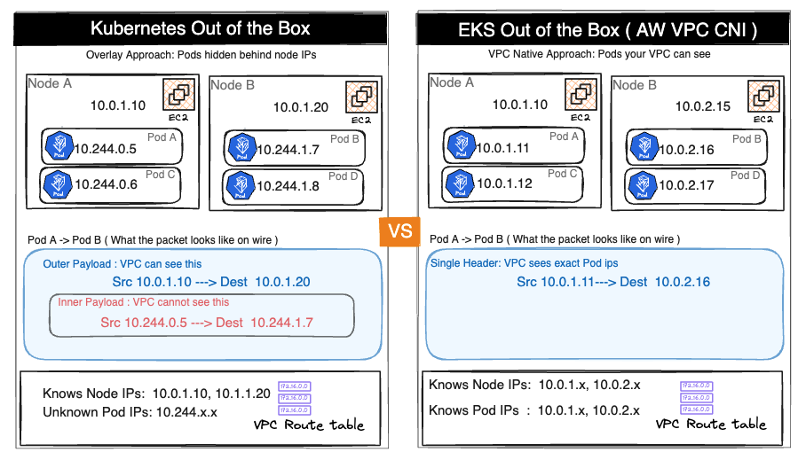
The upside is real. Flow Logs record actual pod IPs. ALBs in IP mode route directly to pods without a NodePort hop. Security groups can be applied at pod granularity via Security Groups for Pods. AWS services, PrivateLink endpoints, and Direct Connect connections all see real pod addresses.
So is the cost.
Every pod consumes a real VPC IP address. A 200-node cluster running 30 pods per node holds 6,000 pod IPs in your subnets — before accounting for node IPs, ENI primary IPs, and the warm pool ipamd pre-allocates on every node. In a /24 with 254 usable addresses, this arithmetic becomes a crisis fast.
That’s the trade AWS made. VPC visibility in exchange for IP pressure. Everything that follows in this post — ipamd, the warm pool, ENI limits, prefix delegation — is the engineering that manages that pressure.
Section 2 — ipamd: the daemon that runs before your pod does
Before your pod exists, ipamd is already working.
ipamd is a long-running daemon inside the aws-node DaemonSet running on every EKS node. Its entire job is to make sure you never wait for an EC2 API call when a pod needs an IP. It runs those calls in advance, keeps the results in a pool, and hands them off the moment kubelet asks.
This matters because EC2 API calls are slow. Attaching a new ENI takes 3 to 10 seconds. Assigning secondary IPs takes another 1 to 3 seconds. If every pod start waited for these calls, a burst of 20 pods during a scale-out event would take minutes. ipamd front-loads the slow work so your pod start is fast.
Two binaries, one DaemonSet
Inside aws-node, two separate binaries handle two separate concerns. Most engineers conflate them. That conflation makes debugging harder.
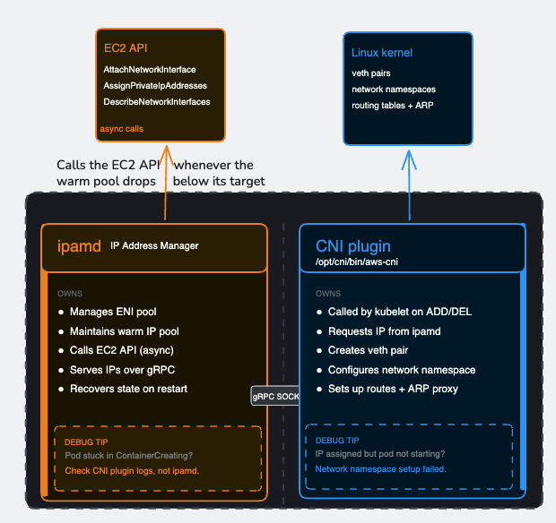
ipamd manages the pool. The CNI plugin consumes from it. Their boundary is the gRPC socket — and understanding where one’s responsibility ends and the other’s begins is the difference between a 10-minute debug session and a 3-hour one.
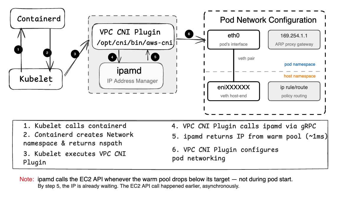
When a pod starts, kubelet invokes the CNI plugin binary directly. The CNI plugin calls ipamd over the socket, gets an IP in roughly a millisecond, then — entirely on its own — creates the veth pair, configures the pod’s network namespace, sets up routing rules, and returns success to kubelet. ipamd does not touch the Linux network stack. It does not create veth pairs. It does not set up routes. Once it hands off the IP, its job for that pod is done.
How a pod gets its network interface on EKS
This matters when you’re diagnosing a pod stuck in ContainerCreating. If ipamd handed off an IP successfully but the pod still hasn’t come up, the problem is in the CNI plugin’s network namespace setup — not in ipamd. Looking at ipamd logs won’t help. Looking at CNI plugin logs will.
The warm pool
ipamd’s central mechanism is the warm pool — a buffer of pre-allocated IP addresses sitting ready before any pod requests them.
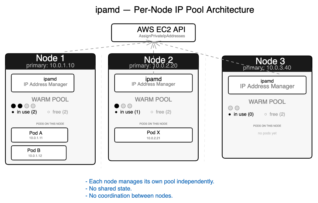
On startup, ipamd recovers existing ENI state from EC2, reconciles against running pods from kubelet, then fills the pool to its target. In steady state, it serves IP requests from the pool instantly and refills asynchronously in the background.
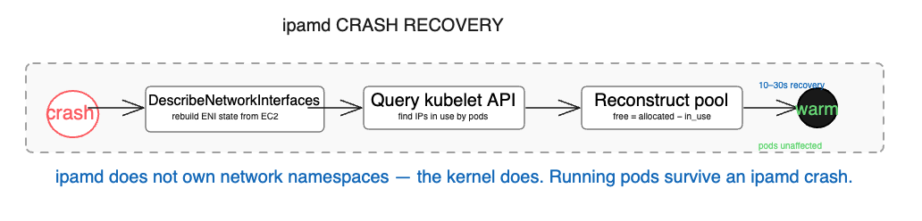
The startup sequence matters beyond normal operations. When ipamd crashes on a node with running pods, it recovers by calling DescribeNetworkInterfaces to rebuild ENI state from EC2 — this data lives in EC2, not in ipamd’s local memory. It queries kubelet to find which IPs are in use. It reconstructs the warm pool from the difference. Running pods are completely unaffected — their network namespaces live in the kernel, and ipamd doesn’t own them. The only consequence of a crash is that new pods cannot start until ipamd recovers, which typically takes 10 to 30 seconds.
Warm pool configuration
Three environment variables control the pool target. They are evaluated in priority order — WARM_IP_TARGET first, MINIMUM_IP_TARGET second, WARM_ENI_TARGET as the default fallback when neither of the others is set.
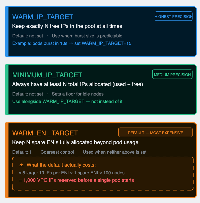
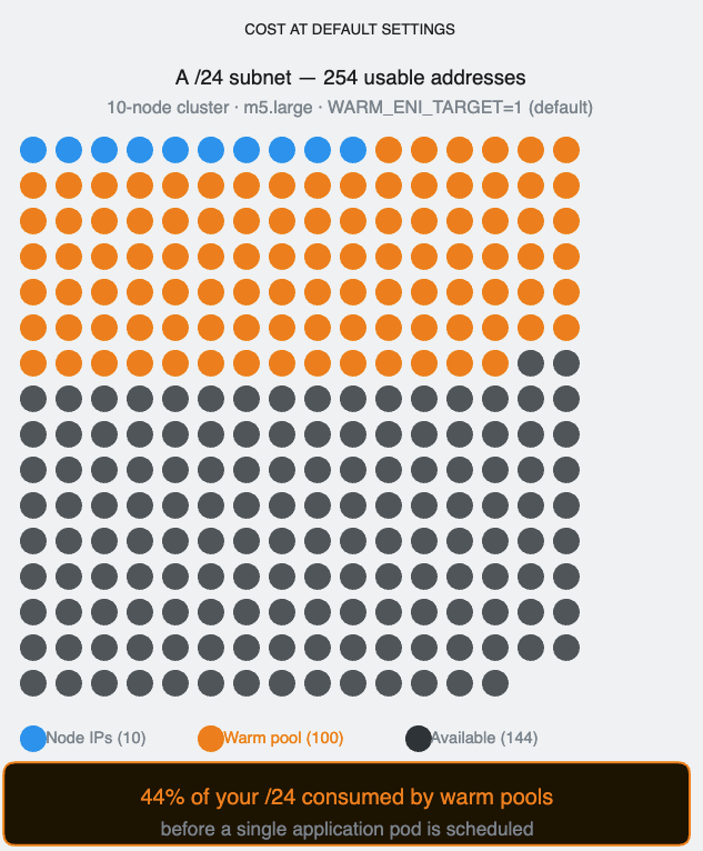
The default WARM_ENI_TARGET=1 is where most teams get hurt without realizing it. An m5.large holds 10 secondary IPs per ENI. With the default setting, every idle node permanently reserves 10 VPC IPs that no pod is using. In a 100-node cluster that’s 1,000 IPs consumed by warm pools before a single application pod is scheduled. In a /24 subnet with 254 usable addresses, warm pools alone consume nearly 40% of the space.
Set WARM_IP_TARGET and MINIMUM_IP_TARGET explicitly based on your actual burst pattern. Reserve WARM_ENI_TARGET for situations where you genuinely need ENI-level pre-allocation — high-throughput nodes where a full ENI’s worth of IPs is regularly consumed in seconds.
Section 3 — Inside the pod’s network namespace
Run ip route inside any EKS pod:
default via 169.254.1.1 dev eth0
169.254.1.1 dev eth0 scope link
There is no host at 169.254.1.1. It’s a link-local address in the IANA-reserved range. Nothing on your network lives there. The pod has a default gateway that doesn’t exist, and it is communicating normally.
This is the thing that confuses almost every engineer the first time they look at EKS pod networking from the inside. Understanding it requires three Linux primitives: network namespaces, veth pairs, and proxy ARP.
Network namespaces
A Linux network namespace is an isolated copy of the network stack — its own interfaces, its own routing table, its own ARP table, its own iptables rules. A process inside a namespace sees only what’s in that namespace. It cannot see the host’s eth0. It cannot see other pods.
Every EKS pod runs in its own network namespace. The host node has its own. For a pod to communicate with anything outside — another pod, a service, the internet — traffic must cross a namespace boundary.
veth pairs
A veth pair is a virtual Ethernet cable with two ends. Anything injected into one end immediately appears on the other. The CNI plugin creates one veth pair per pod at startup:
- One end, named eth0, lives inside the pod’s namespace. This is the interface the pod sees.
- The other end, named eniXXXXXX, lives in the host namespace. This is how the host handles the pod’s traffic.
The 169.254.1.1 trick
The pod needs a default gateway. Without one it can only talk to itself. The obvious candidates — the node’s primary IP, another pod’s IP — create ordering dependencies and portability problems. The CNI plugin uses 169.254.1.1, a link-local address guaranteed not to conflict with any real infrastructure.
When the pod wants to send a packet anywhere, it ARP-resolves its gateway first: “who has 169.254.1.1?” The CNI plugin has already installed a proxy ARP entry on the host side of the veth pair — eniXXXXXX answers that ARP request with its own MAC address. The pod receives the reply, caches it, and believes it has a working gateway. Every outbound packet goes to that MAC, crosses the veth into the host namespace, and from there the host’s routing table and policy rules take over.
The gateway is a controlled fiction. Real routing happens entirely in the host namespace.
One detail that matters: it’s the CNI plugin that sets up this ARP proxy — not ipamd. ipamd’s job ends at handing off the IP. Everything that touches the Linux network stack, including 169.254.1.1, is the CNI plugin’s responsibility.
Per-ENI routing tables
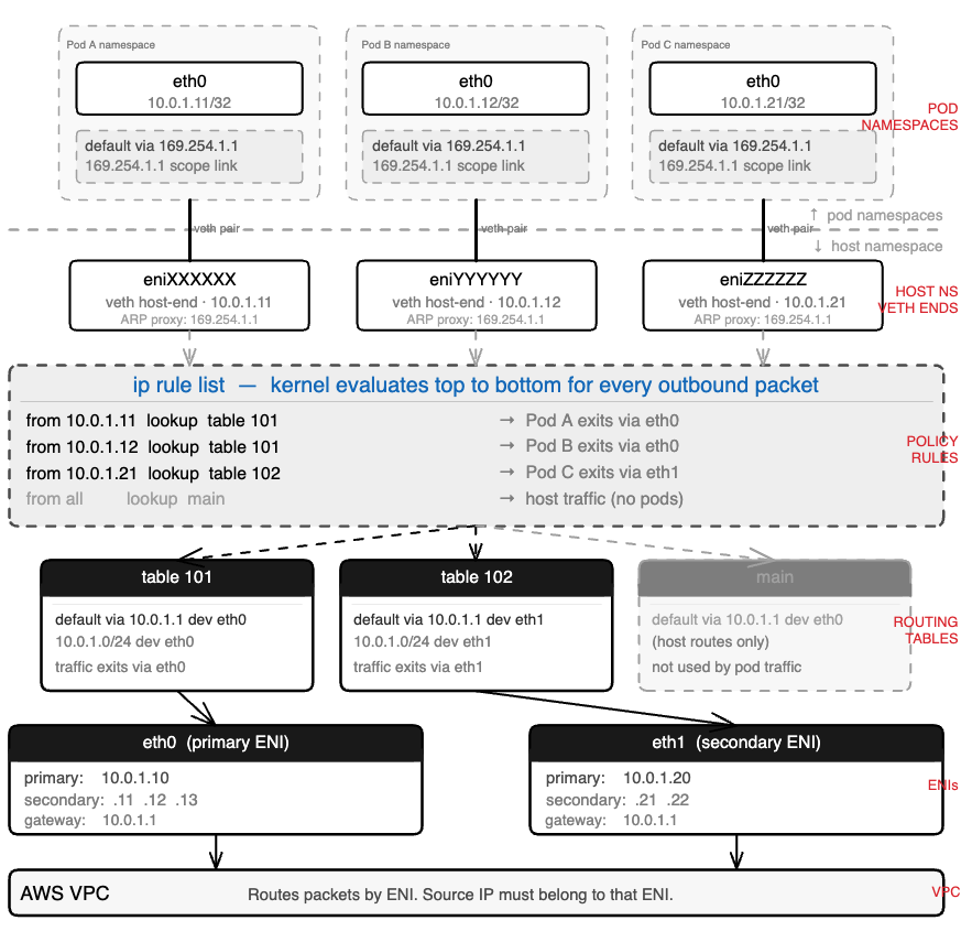
Each secondary ENI gets its own routing table in the host namespace. Each pod IP gets a policy routing rule that maps it to the correct table.
When a packet from Pod A (10.0.1.11) arrives in the host namespace via the veth, the kernel checks ip rule list. It finds from 10.0.1.11 lookup table 101. Table 101 has a default route via eth0. The packet exits through eth0 — the ENI that Pod A’s IP belongs to.
Without these per-source rules, a pod whose IP came from eth1 might send traffic through eth0. The VPC sees a packet sourced from an IP that doesn’t belong to that ENI and drops it silently. No error. The sender times out. This is one of the harder-to-diagnose failure modes in EKS networking — we’ll see it in detail in Section 5.
Why pod IPs are /32
Pod IPs are assigned as /32 host routes, not as members of a subnet. This means the pod has no direct L2 connectivity to any other address. Every packet, regardless of destination, goes through the default gateway, crosses the veth, and enters the host routing stack.
The consequence is simplicity at scale. The host doesn’t need a bridge or an L2 domain shared across pods. Each pod has exactly one route, one policy rule, one veth pair. The model scales linearly. Adding the 50th pod to a node is identical to adding the 5th.
Section 4 – The ENI limit nobody warns you about
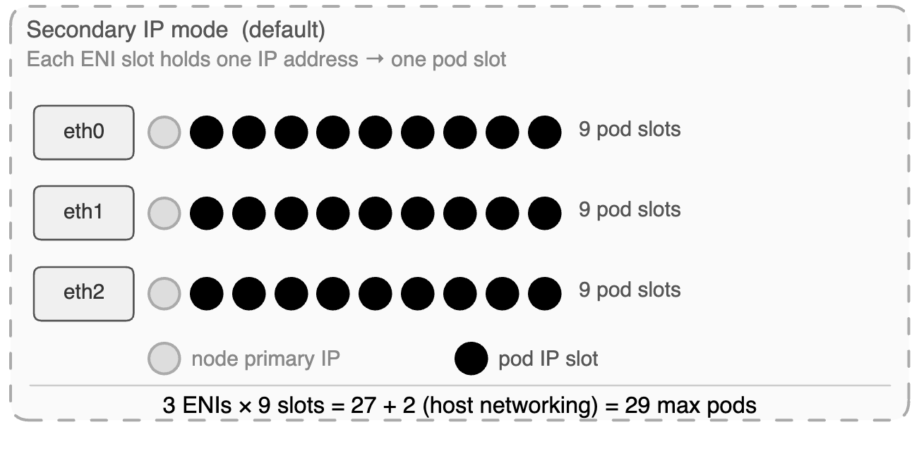
Every EC2 instance type has hard limits on how many ENIs it can attach and how many secondary private IPs each ENI can hold. These limits are not configurable. They are physical constraints baked into the instance type by AWS. And they directly determine the maximum number of pods a node can run.
The formula:
max_pods = (max_ENIs × (IPs_per_ENI – 1)) + 2
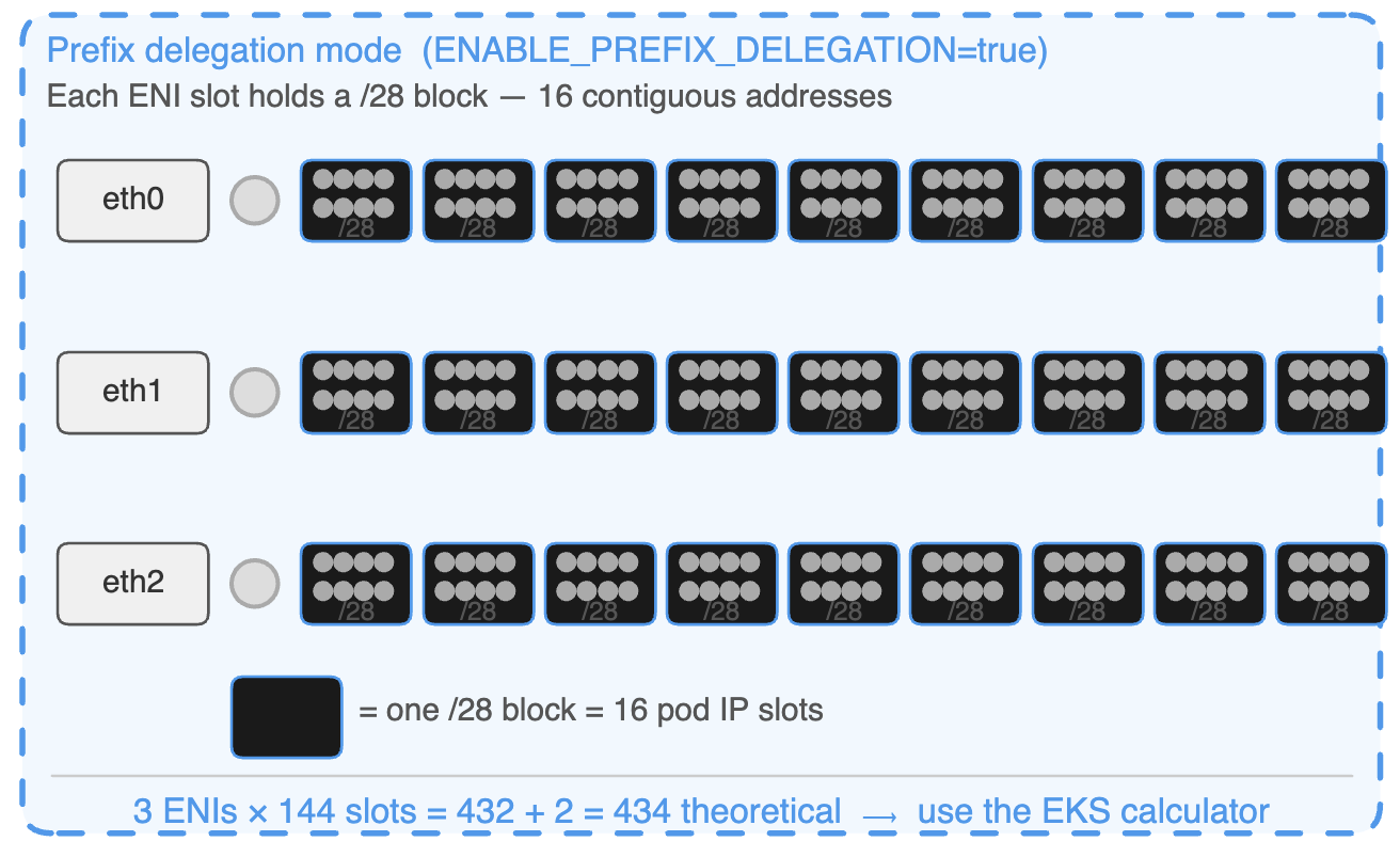
Prefix delegation
Prefix delegation changes the unit of IP assignment from individual addresses to /28 blocks — 16 contiguous IPs per block. One ENI slot that previously gave one pod IP now gives sixteen.
Instance type | ENIs | IPs / ENI | Secondary IPs / ENI | Max pods (secondary IP mode) |
t3.small | 3 | 4 | 3 | 11 |
t3.medium | 3 | 6 | 5 | 17 |
m5.large | 3 | 10 | 9 | 29 |
m5.xlarge | 4 | 15 | 14 | 58 |
m5.2xlarge | 4 | 15 | 14 | 58 |
m5.4xlarge | 8 | 30 | 29 | 234 |
c5.xlarge | 4 | 15 | 14 | 58 |
c5.4xlarge | 8 | 30 | 29 | 234 |
c5.18xlarge | 15 | 50 | 49 | 737 |
Instance type | ENIs | Secondary slots / ENI | /28 blocks / ENI | Pod slots / ENI | Theoretical max pods | Recommended –max-pods |
t3.small | 3 | 3 | 3 | 48 | 146 | ~57 |
t3.medium | 3 | 5 | 5 | 80 | 242 | ~67 |
m5.large | 3 | 9 | 9 | 144 | 434 | ~110 |
m5.xlarge | 4 | 14 | 14 | 224 | 898 | ~110 |
m5.2xlarge | 4 | 14 | 14 | 224 | 898 | ~110 |
m5.4xlarge | 8 | 29 | 29 | 464 | 3,714 | ~234 |
c5.xlarge | 4 | 14 | 14 | 224 | 898 | ~110 |
c5.4xlarge | 8 | 29 | 29 | 464 | 3,714 | ~234 |
c5.18xlarge | 15 | 49 | 49 | 784 | 11,762 | ~737 |
The subnet requirement
Prefix delegation requires 16 contiguous addresses aligned to a /28 boundary in the subnet. If your subnet is fragmented — individual IPs scattered across the address space from years of other workloads — EC2 may fail to assign a /28 even when total free addresses are sufficient. This failure is invisible in the console until allocation fails and pods don’t come up.
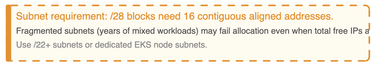
Prefix delegation works reliably on subnets that are either large enough that fragmentation doesn’t matter (/22 or bigger) or dedicated to EKS nodes and not shared with other workloads. Dedicated node subnets are the right architecture for any cluster beyond small scale. They make the IP math transparent and eliminate the fragmentation problem entirely.
Migration: new node group, not in-place drain
Prefix delegation only takes effect on new nodes. The operationally safe migration path is to provision a new node group with prefix delegation configured from the start, migrate workloads across, and delete the old group.
Enabling the flag and draining existing nodes in place risks nodes coming up in a mixed state — some ENIs holding individual IPs from the old configuration, some holding prefixes from the new one. The resulting inconsistent capacity reporting is painful to diagnose under pressure.
The secondary CIDR escape
If your VPC is running low on address space and you can’t get more IPv4 range from your network team quickly, there is one more option worth knowing.
AWS supports associating a secondary CIDR from the 100.64.0.0/10 range with your VPC. This comes from RFC 6598 — originally defined as carrier-grade NAT space. It is fully routable within AWS but does not appear on the public internet. Your pods get IPs from this range, freeing your primary VPC CIDR for everything else.
A 100.64.0.0/10 block gives you over 4 million addresses. It won’t solve a fundamentally broken subnet architecture, but as runway while you plan a proper fix it’s the fastest path available without a VPC redesign.
Section 5: How this breaks in production
The three failure patterns below account for the majority of EKS IP allocation incidents. They share a common feature: they present application problems until you know where to look.
Pattern 1 — The pod start latency cliff
What you see: Pod start times are consistently under 2 seconds. Then, during a scale-out event, they spike to 15–30 seconds with no change to the application or deployment configuration.
What’s actually happening: The warm pool is sized correctly for normal operations but too small for the burst rate of a large scale-out. When the autoscaler provisions 30 new nodes simultaneously, each node’s ipamd starts filling its warm pool at the same time. The combined EC2 API call volume across the fleet triggers throttling. AssignPrivateIpAddresses calls that normally take 1 second start taking 10–20. The pool can’t refill fast enough. Pods that arrive after the pool empties wait for synchronous EC2 API calls before they get an IP.
Fix: Increase WARM_IP_TARGET so each node pre-allocates more IPs during bootstrap before competing with the rest of the fleet. Consider prefix delegation — each EC2 API call assigns 16 IPs instead of 1, cutting total call volume by 16x during scale-out.
Pattern 2 — Subnet exhaustion from warm pool leak
What you see: New nodes fail to provision. Pods on existing nodes fail to start. ipamd logs show InsufficientFreeAddressesInSubnet. The subnet in the AWS console shows near-full address usage, but the number of running pods doesn’t explain it.
What’s actually happening: ipamd is holding more IPs than pods are using. This happens in two ways. First, WARM_ENI_TARGET=1 on a large fleet permanently reserves a full ENI’s worth of IPs per node — on 100 m5.large nodes that’s 1,000 IPs sitting in warm pools. Second, after a cluster scales out and back in, the remaining nodes may still hold warm pool IPs sized for the peak fleet rather than the current one. ipamd is conservative about releasing IPs to avoid churning EC2 API calls.
Fix: Replace WARM_ENI_TARGET with explicit WARM_IP_TARGET and MINIMUM_IP_TARGET values sized to your actual burst pattern. This gives ipamd clear boundaries for when to release IPs rather than holding a full ENI in reserve indefinitely.
Pattern 3 — The asymmetric routing silent drop
What you see: Intermittent connection failures between pods on different nodes. Not all connections fail — just some, with no apparent pattern by service, time of day, or node. tcpdump on the sending pod shows packets leaving. The receiving pod never sees them. No error is returned to the application. Connections time out.
What’s actually happening: A pod whose IP was assigned from eth1’s secondary pool is sending traffic through eth0. The VPC sees a packet arriving via Node A’s eth0 ENI with a source IP that belongs to Node A’s eth1 ENI. It interprets this as spoofed source traffic and drops it silently.
This happens when the policy routing rules in the host namespace are incomplete. Each pod IP needs a rule mapping it to the correct ENI’s routing table. If ipamd crashed mid-allocation and the CNI plugin was invoked before recovery completed, the rule may be missing. The pod’s traffic falls through to the default routing table, exits via the wrong ENI, and the VPC drops the return path.
The long-term fix is alerting on ipamd restarts and verifying routing rule consistency after any ipamd recovery. A missing policy rule is the silent result of a race condition between ipamd recovery and pod scheduling — it won’t appear in application logs, and it won’t appear in Kubernetes events. It only shows up when you look directly at the host network namespace.
Summary
You have a complete mental model of how EKS pods get their IP addresses.
The VPC CNI gives every pod a real VPC IP rather than running an overlay. That decision unlocks native AWS integrations — Flow Logs that record actual pod IPs, load balancers that route directly to pods, security group enforcement at pod granularity via SG for Pods. It also creates IP pressure that has to be managed deliberately: warm pool sizing, subnet planning, ENI limits, prefix delegation.
ipamd front-loads the slow EC2 API work so pod starts are fast. The CNI plugin handles the Linux side — veth pairs, network namespaces, the 169.254.1.1 ARP proxy, per-ENI routing rules. These are separate binaries with a clean boundary between them, and knowing where that boundary is cuts debugging time significantly.
The ENI limits are real and they bite teams that don’t plan for pod density independently from compute requirements. Prefix delegation solves the capacity problem but requires the right subnet setup and a clean migration path. The warm pool default burns more IPs than most teams realize until they’re diagnosing subnet exhaustion under pressure.
Next: Post 2 — The Packet Journey